


Led driver metal stamping components supplier in China
 January 17, 2019
Timeplex Industrial Limited speclizes in LED Driver Metal Housing for Osram ,BAG for morethan 20 years .Have full experiences in the led driver ,led power Metal stamping components for the market .We also know the LED driving power supply is a voltage converter that converts the power supply into a specific voltage and current to drive the LED to emit light. Usually, the input of the LED driving power source includes high-voltage power frequency alternating current (ie, mains), low-voltage direct current, high-voltage direct current, low voltage high. Frequency communication (such as the output of an electronic transformer). The output of the LED driver is mostly a constant current source that changes the voltage as the LED's forward voltage drop changes. This article introduces the common LED driver power supply circuit diagram.
LED driver power supply circuit diagram one----capacitor buck power supplyC1 is a step-down capacitor (using a metallized polypropylene capacitor) and R1 provides a discharge loop for C1. Capacitor C1 provides a constant operating current for the entire circuit. Capacitor C2 is an electrolytic capacitor, and its withstand voltage depends on the number of LEDs connected in series (about 1.5 times its total voltage). Its main function is to suppress voltage abrupt changes caused by energization moments, thereby reducing voltage shock. The impact on LED life. R4 is the bleeder resistor of capacitor C2, and its resistance should be increased as the number of LEDs increases.
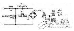
It should be noted that the circuit must select the appropriate capacitor according to the current of the load, not the voltage and power of the load. Generally, the relationship between the capacity C of the step-down capacitor C1 and the load current IO can be approximated as: C=14.5IO, The unit of capacity of C is uF, and the unit of Io is A. The current limiting capacitor must use a non-polar capacitor, and the capacitor's withstand voltage must be above 630V.
LED drive power circuit diagram II----traditional low efficiency circuitThe following figure is a traditional low-efficiency circuit. The grid power supply is stepped down by a step-down transformer. After bridge rectification and filtering, the three LEDs are stabilized by resistor current limiting. The fatal disadvantage of this circuit is that the existence of resistor R is necessary. The active loss on R directly affects the efficiency of the system. When the R partial pressure is small, the voltage drop of R accounts for 40% of the total output voltage, and the active loss of the output circuit on R has accounted for 40%, plus the transformer. Loss, system efficiency is less than 50%. When the supply voltage fluctuates within ±10%, the current flowing through the LED will change by ≥25% and the power variation on the LED will reach 30%. When the R partial pressure is large, when the power supply voltage is within ±10%, the power variation to the LED can be reduced, but the system efficiency will be lower.
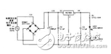
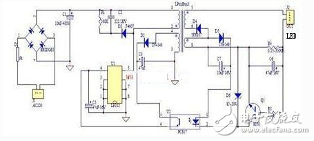
The circuit in the figure below uses capacitor directly as the current limiting component. In this circuit, since the voltage division on the capacitor reaches almost all the power supply voltage, it has good current limiting characteristics. When the power supply voltage fluctuates by ±10%, the output current It also fluctuates within ≤±10%. As long as the LED's rating is left with a certain margin in the design, it can ensure that the LED is still in good working condition when the power supply voltage fluctuates. Since the dielectric loss of the capacitor is extremely small, the loss of the circuit is small. The function of the resistor R is to ensure that the voltage on the capacitor can be discharged in time when the power is turned off, and the resistance value can be ≥3 MΩ, and each group of LEDs in series can be With an IN4007 diode, when two sets of LEDs in series have an internal open circuit, the other group may be reversed by a reverse voltage. If an IN4007 diode is connected in series, the remaining LEDs can be protected from damage. Of course, the IN4007 is added. It also slightly reduces the efficiency (when the output current is 30mA, the power consumption on the IN4007 is about 0.02W). For the integrated night light, the IN4007 can be omitted, and the efficiency of this drive circuit is ≥90%. The LED night light lamp made by the driving circuit is more efficient than the night light lamp using the gas discharge light source, and the service life is much longer than that of the night light lamp using other light sources. This circuit works stably when 30 LEDs are connected in series. However, the light output by this circuit has a certain stroboscopic light (100 Hz stroboscopic at 50 Hz), which is not suitable for lighting applications of moving objects, and the LED should be made inaccessible when used, otherwise it will affect safety.
The voltage is distributed by one IC or multiple ICs, the types of electronic components are small, the power factor and power supply efficiency are very high, electrolytic capacitors are not required, and the life is long and the cost is low. The disadvantage is that the output high voltage is not isolated, there is stroboscopic, and the outer casing is required to be protected against electric shock. The market claims that there is no (go) electrolytic capacitor, and the long life is based on linear IC power. IC drive power supply has high reliability, high efficiency and low cost, and is the ideal LED drive power source in the future.

A transformer is used to change the high voltage to a low voltage and rectify and filter to output a stable low voltage direct current. The switching constant current source is divided into an isolated power supply and a non-isolated power supply. The isolation refers to the output high and low voltage isolation, and the safety is very high, so the insulation of the outer casing is not high. Non-isolated safety is slightly worse, but the cost is relatively low. Traditional energy-saving lamps use non-isolated power supplies and are protected by an insulating plastic casing. The safety of the switching power supply is relatively high (generally output low voltage), and the performance is stable. The disadvantage is that the circuit is complicated and the price is high. Switching power supply technology is mature and stable, and it is the mainstream power supply for LED lighting.
The above is the Led driver metal stamping components supplier in China we have listed for you. You can submit the following form to obtain more industry information we provide for you.
You can visit our website or contact us, and we will provide the latest consultation and solutions
Send Inquiry
Most Popular

lastest New

Related Products


Send Inquiry